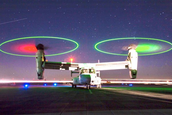
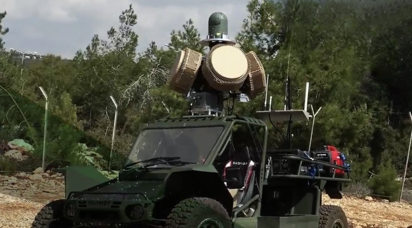
Long range EOIR Thermal imaging FLIR Stabilized HD MWIR SWIR Zoom gimbal turret
for vehicle mobile, marine ocean and aerial airborne manned and unmanned Security applications.

GSA NDAA 889 approved Vehicle mobile, marine ocean and aerial airborne Long range EOIR Thermal imaging FLIR Stabilized camera.
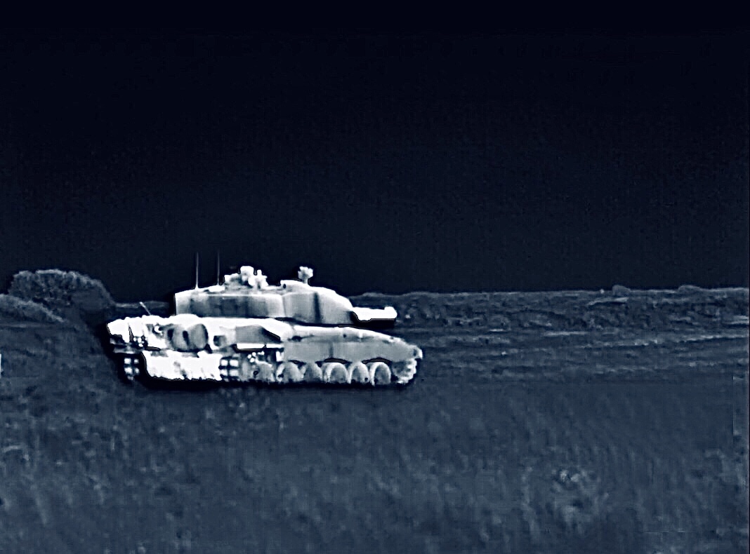
The system is ideal for fighting attack armored vehicles, CUAS anti-multi Drone UAV UAS Countermeasures, RWS Remote weapon stations and a variety of exotic non traditional overmatch EOIR
Asymetrical remote sensing/remote viewing Applications where long distance, far standoff user protection, stealth covertness, precision and accuracy is essential.
If you are looking for the absolute best, most rugged long standoff range EO/IR, Day and night vision range finding camera systems that’s stabilized,
the S25 series of gimbals is a viable solution.
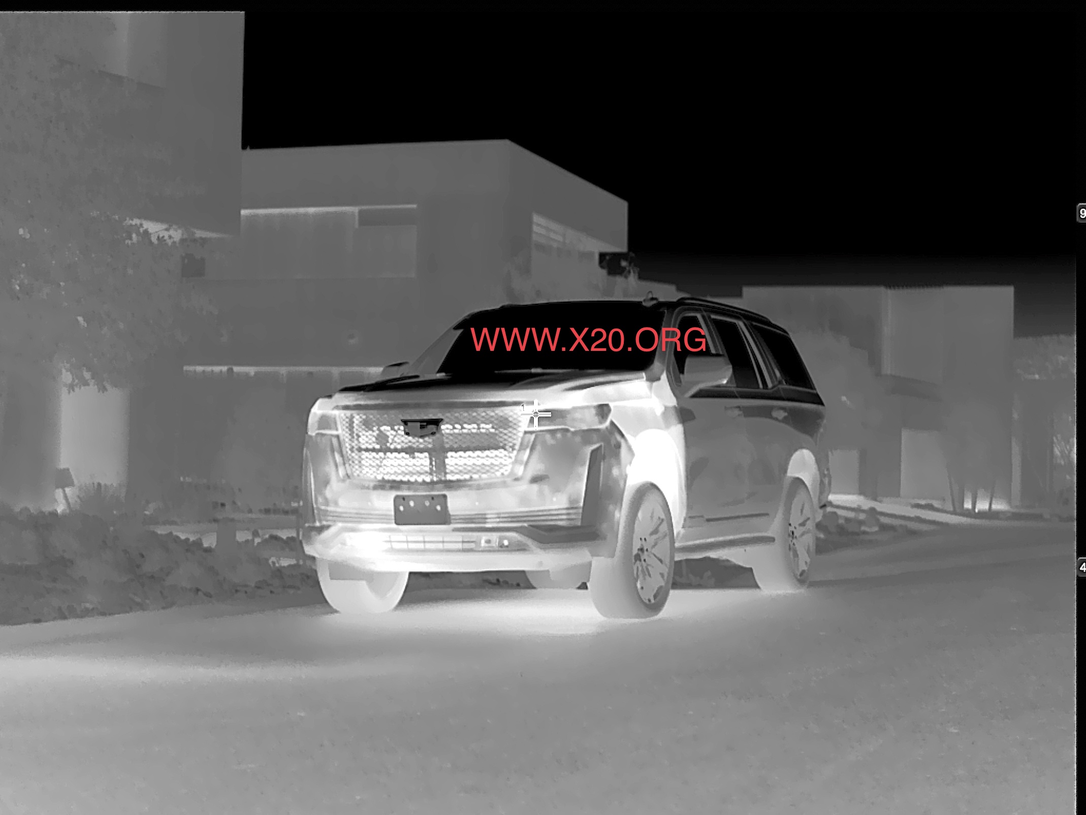
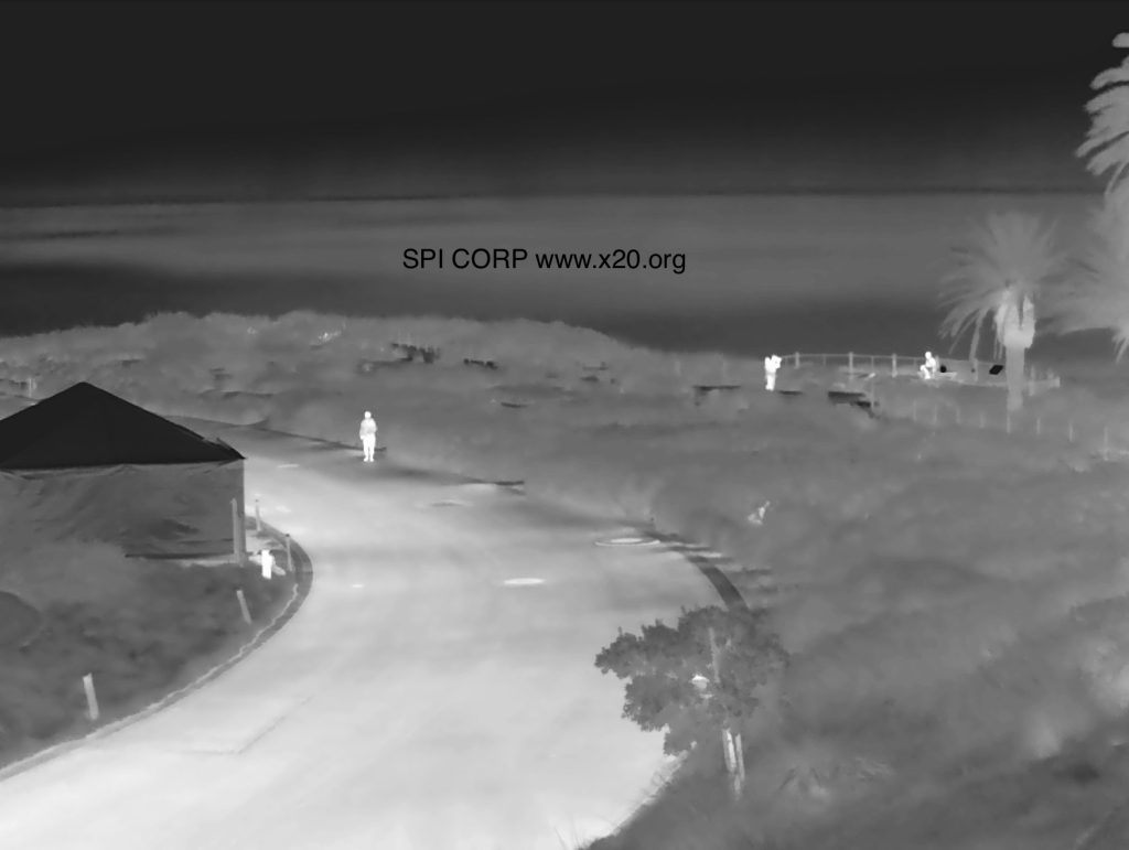
The system can be used as a wide FOV Field Of View DVE Drivers Vision enhancement for navigation while offering long range day/night imaging with exceptional DRI.
The simple to use, mount and learn platform is fully mil spec offering the user local and remote imaging in the harshest of environments.
SYSTEM OVERVIEW
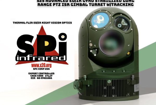
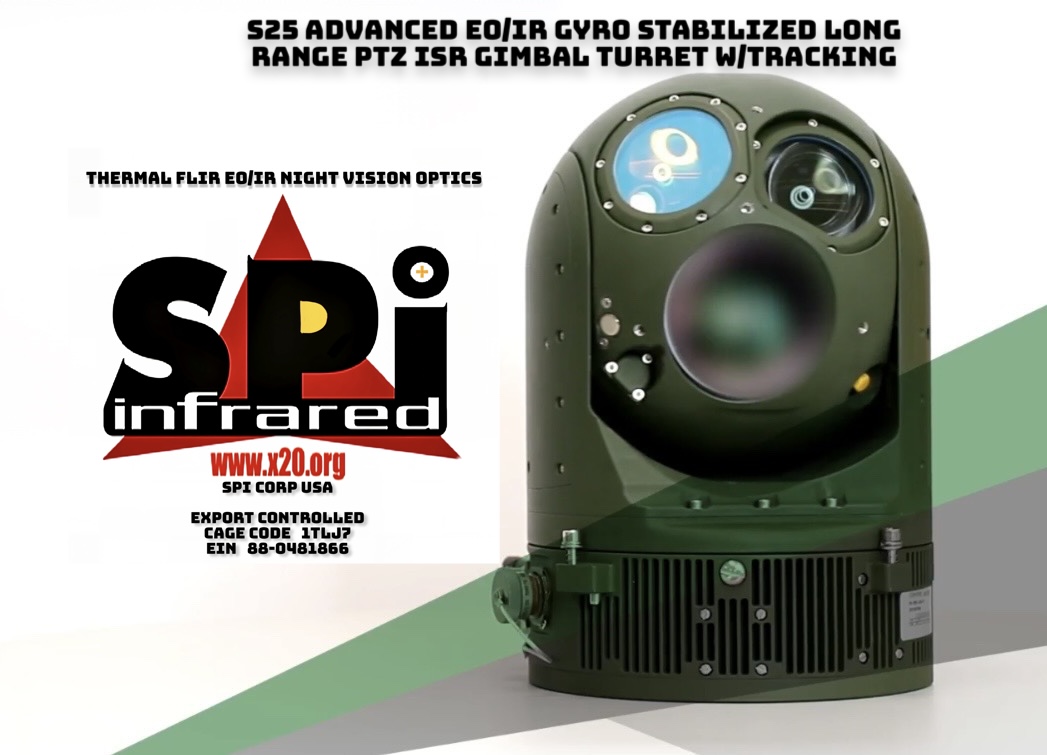
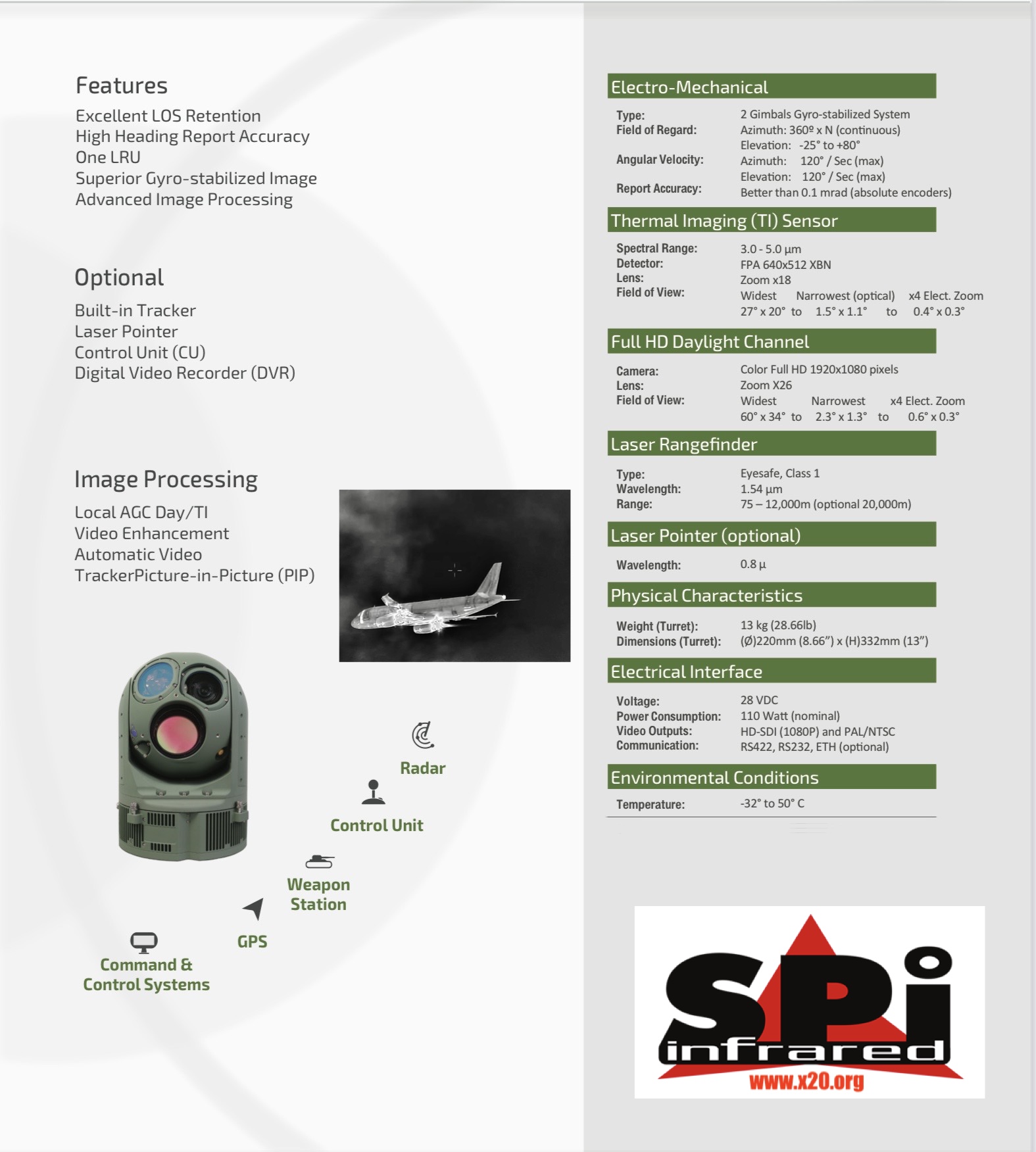
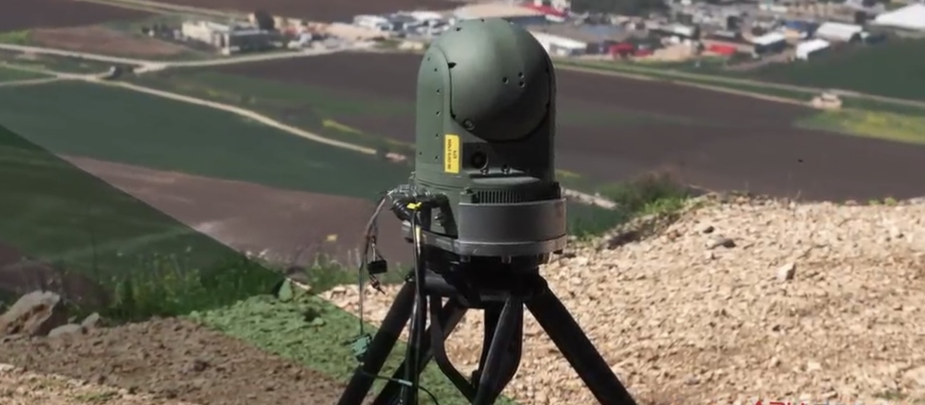
This data is a technical description for the high definition (HD) Observation intelligence surveillance recognition (ISR) and weapon director, optronic payload.
S25-HD is a lightweight single LRU, four sensors dual gimbal actively stabilized and remotely controlled. It contains IR sensor, full HD DTV sensor, laser range finder (LRF)and option for laser pointer (LP).
S25-HD is part of SPI family of ground, naval and airborne payloads which are used successfully on board of variety ground armored vehicle and marine crafts used in-military and para-military applications. The S25-HD is under full rate production.
The EO full HD consists of a 1920×1080 pixels sensor (1080p). The IR detector is a 640×512 focal plane array (FPA) pixels. Optional High sensitivity HD High Def 1280×1024 SXGA MWIR is available as an upgrade option.
An eye safe, laser range finder (LRF) sensor. All are mounted on the line of S25 (LOS) of the payload, aligned with the EO and IR images LOS.
This video output is carried over HDSDI interface. In addition, analog standard (NTSC or PAL) video is output simultaneously and in parallel to the HDSDI. The two sceneimages IR and DTV can be monitored simultaneously on the user monitors.
The payload is controlled by computerized control unit (CU) and power by a standard military (ground vehicle or naval craft)24/28 DC voltage supply
Dual gimbals axes, actively stabilized line of S25 (LOS).

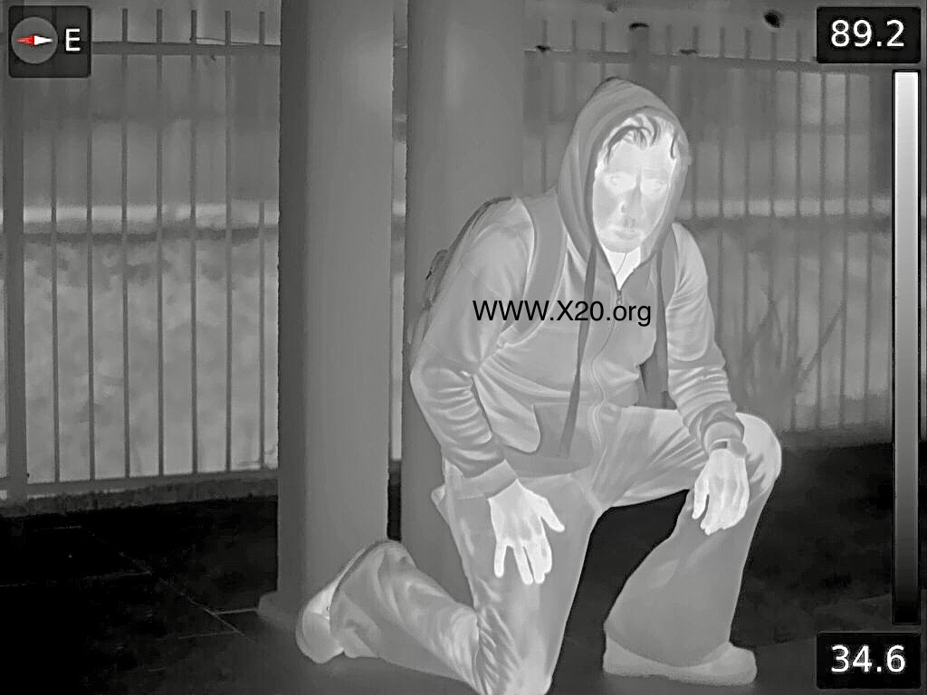
AI + Long Range stable Thermal IR infrared FLIR (Forward Looking Infrared) imager with CZ continuous optical zoom and alternative four pre-set discrete optical FOVs.
DTV Day LLL Low Light Level Television Camera with continuous F1.4 optical zoom and Near IR (NIR) capability, with image enhancement, anti fog, anti haze turbulance mitigation,
Two (2) Simultaneously stereo Bi Spectral BI Spectrum dual switchable standard video (AV) outputs, one for the IR camera and one for the EO camera. (EO/IR)
Daytime visible CMOS BSI Low Light and IR Infrared Mid Wave 3-5 micron images enhancement algorithm.
Eye safe 1550 laser range finder that measures range to viewed target.
Remote control via serial bi-directional communication. Also available is a dedicated hand held 4 axis JoyStick with Keypad that allows a direct control on payload.
Alternatively PC with dedicated Man+Machine Interface (MMI) console.
 Full HD screen of the maximum diagonal (inches), depending on the space available.
Operates from standard armor vehicle or naval craft power source of 28 VDC.
The system is fully MILSPEC and conform with multiple MIL STDS
The payload supports the following modes of operation:
- Power-up: The payload completes power up Gimbals are powered inidle mode. Full communication is established. All sensors are active. IR cooler runsTI and DTV output image. LRF and LP are blocked from output energy.
- Rate: The LOS is locked on to a specific inertial direction in Gimbal servoloops are active and the LOS is stabilized. Rate commands will slew the LOS inelevation or in yaw.
- Position: The LOS is locked at a fixed angle relative to the carrying Gimbal servo loops are active and the LOS is stabilized. Rate commands willslew the LOS in elevation or in yaw.
- Forward: The LOS is locked at a fixed angle relative to the carrying platform forward (0 Az & 0 El). Gimbal servo loops are active and the LOS is Rate commands are ignored.
- Stow: The LOS is locked in an back and maximum upward position in order toprotect the system windows during idle (Such or non- operation travel of the platform).
- Laser Ranging: LRF fires measures and report range to target at center of the To range, LRF must be at active ARM state.
- Slave:LOS pointing is slaved to an external source of AZ & EL data, typically maritime

3.2.1 Power
The payload is powered by a 24VDC vehicle power supply (22-32) in accordance withMIL-STD-704E. Power consumption at nominal operation, is less than 80 Watts. Maximumis less than 120W and peak power at start up is less than 180W.
3.2.2 Communication
Communication control and status to/from the payload is via a serial RS-422 bi-directional full duplex channel at 115,200 BPS. The protocol contents are in accordancewith SW Protocol document.
Communication supports the required data rate for gunnery control.
3.2.3 Electrical ICD
The payload interfaces via the following functional connectors.
J1: Serves as the input/output Payload power and signals connector.
J2: Serves for HDSDI video format, output.
J3:Serves for maintenance purposes.
3.2.1 Video Interface.
The payload interface with the following video outputs
3.2.1.1 HD Format.
Full HDSDI format, switchable between DTV and IR. SMPTE 292M format of 1920x1080p25/30.
3.2.1.2 Analog video (AV) Video Format.
Two AV video outputs are available in a standard analogue format of NTSC (or PAL) factoryset. The two outputs are available simultaneously. The prime video output carries alsothe payload build-in overlaid symbology.
3.2.2 Mechanical Interface.
The S25-HD interfaces to its carrying vehicle by means of six screws on the fixedcarrying plate, which allows:
- High accurate reference plane for direct mount of the payload to the carrying vehicle, or
- Useofshockmountsviaa”spiderstyle”mechanical
3.2.3 Interface with other sensors:
The S25-HD can be connected with other sensors and radars
 3.2.1 Size and weights.
Turret Ball diameter:
Payload height: 332 mm.
Gimbal weight: 13 Kg. ( 29 lb)
 S25-HD Sensors Characteristics

3.3.1 Turret and LOS.
Angular spatial coverage. (for Ball up orientation) Elevation angle dynamic range : +85° to -20°
*note: Below -25° observation capabilities are degraded due to gimbal obstruction
Azimuth angle dynamic range : 360° x N
Rate – azimuth and elevation : ±0.25° to ±60°/sec (FOV dependent) Acceleration azimuth and elevation: > 60°/sec2
Attitude report Accuracy (El and AZ): Better than 0.2 mrad
Angular drift: < 6° /Hr
Typical LOS stabilization level: 15-50 micro radian RMS
3.3.2 IR Sensor
3.3.2.1 Detector Characteristics
Spectral band:
Array format: 640 x 512 pixels. 10-micron pitch. Uniformity:
Two points factory correction. Onepoint user access.
Cooler: Close loop linear cooler. Less than 8 min cool downtime.
Table selection: Three user selectable tables. (To cover the operational temperature scene)
 3.3.1.1 Field of View
TI Continuous zoom mode: Optical :
27×21 – 1.47×1.17 (X18 zoom).
Electronic X4: 1.47×1.17 – 0.36×0.29
TI Pre-set FOVs.
The TI can operate in four pre-set FOVs (factory set) for fast FOV switch, which can be configured.
3.3.1.2 TI Controls and Modes of operation
TI image has the following image automatic gain level control (AGC):
Automatic: Image quality is set automatically by the system. This selection can be appliedon a selected region from the scene.
Local Area: AGC uses a non-linear base algorithm. This selection can be appliedon a selected region from the scene.
Enhancer: The user can select to sharpen the image to depict details in the scene.
Manual: The user controls manually the image Gain and Level to depict specific items inthe scene.
Focus control: Manual control of IR image focus. Automatic when switching FOV, to the last set or to infinity.
Image freeze.
3.3.1 Color DTV Channel
3.3.1.1 Format
The DTV sensor utilizes a Full HD color image 1920×1080 pixels in parallel to standard analogue output. It has a built in image enhancer based on color boost and-contrasts enhancement.
3.3.1.2 DTV Characteristics
Number of pixels:
Sensitivity: color 0.4 lux ; B/W 0.1 lux
Focus: Auto / Manual control.
Iris: Auto / Manual. (user selectable F1.6 to F28)
Shutter: Auto (1/15 to 1/10,000).
Gain: Automatic.
Image freeze: Yes.
Lens type : Continuous zoom FOVs:
a. HD output:60– 2.1Optical Horizontal 2.1– 0.6Elec. Horizontal.b. AV output:40– 0.9 Optical Horizontal.
Pre-set FOVs:
0.9– 0.15Elec. Horizontal.
- HD output:59, 16, 3, 2.1 Horizontal.
- AV output: 22, 6.0, 2.0, 0.8 Image Enhancer: Color boost, Contrast enhancement.
Near IR: Yes, 0.4 1.1 Micron remote controlled.
Ultra light eoir thermal imaging FLIR EO + IR Day/Night Gimbal for manned and unmanned applications
HD drone thermal imaging flir EOIR gyro-stabilized gimbal turret ball
Custom OGI VOC gas optical imaging and detection thermal flir imaging camera systems
We specialize in:
-Thermal FLIR and multi sensor Rifle Scopes (including used low cost models)
-Custom FPGA design and rapid 3d prototype
-sensor blending and image fusion up to 10 channels
-long range laser cameras, HD CMOS & thermal imaging detectors cores & cameras
-long range HD visible and thermal superzoom telephoto continuous zoom optics
-mwir ultra extreme long range thermal Flir thermal infrared imaging cameras
-lwir long range continuous zoom uncooled thermal Flir infrared imaging cameras
-cmos night vision cameras and sensors
-Image fusion, Sensor fusion Image blending
-Image stabilization, gyro/mems/motors for payloads, turrets, balls & Gimbals
-llltv cameras and sensors, lenses/optics from visible, SWIR, MWIR, LWIR to VLWIR
-color low light level night vision sensors and camera modules, cores and engines
-Infrared Cameras (scientific, military, R&D and maintenance models)
-Thermal Imager Systems (law enforcement and military thermal imaging models)
-Thermal Pan Tilt Zoom (thermal PTZ) Multi-Sensor Systems (custom and COTS solutions)
-Night Vision (image intensified products)
-Night Vision (EMCCD, iccd, i2 products)
-ebaps isie-11 cameras
-electronic digital image intensifiers
-tubeless image intensifiers
-tube image intensifiers
-custom head mounted, hands free goggles, weapon sights, Dve, mobile,marine and airborne platforms
-Digital night vision goggles DNVG
-color night vision goggles
-Dual Sensor Long Range PTZ thermal imaging FLIR cameras
-Multi Sensor Long Range PTZ thermal imaging FLIR cameras
-Dual Sensor Long Range PTZ thermal imaging FLIR / CCTV HD cameras
-Scmos and CMOS custom sensor integration and customization
-ingrated lasers visible and infrared from visible to SWIR
–SWIR ingaas cameras and sensors
-image stabilization, custom gimbals, payloads, turrets from 2 to 5 axis
-drone, Uav, Uav, UAS, suas cameras, STUAS UAV detectors, sensors and imagers
-Systems Integration, custom electro optics / optronics
-Custom Design and Manufacturing
-Kitting Assemblies and Contract Logistics
-VIS/SWIR
-DNVS
-DNVG
-Enhanced Night vision
-NVG
-DI2
-EI2
-TE-Photocathode
-Digital UXGA Low Light Level
-4K imaging
-AI artificial intelligence
-ML machine learning
-Ultra Long Range zoom continuous, DFOV, TFOV optics and Lenses
-HD Microdisplay OLED, HMD, Headmounted optics
-Night vision systems/goggles/weapon sights/rifle mounted scopes/Clip on-Inline sights/Binoculars/cameras/lasers/sensors
-ISR/C4ISR/EOIR/RSTA/UHD MWIR/HOT MCT/HD COOLED ADVANCED FLIR’S