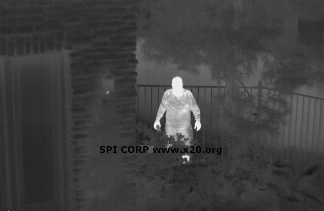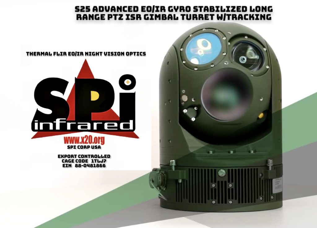
The S25 Series multi sensor PTZ thermal imaging flir is a state of the art EO/IR tracking Range finding all weather rugged turret with precision payload.

The gimbal packs an array of cutting edge sensors / optics made for mobile, fixed, UGV USV land and marine applications. The NDAA GSA approved system is available with rapid delivery.
Available in High Definition HD cooled MWIR midwave HOT IR sensor option
Comes in MilSpec
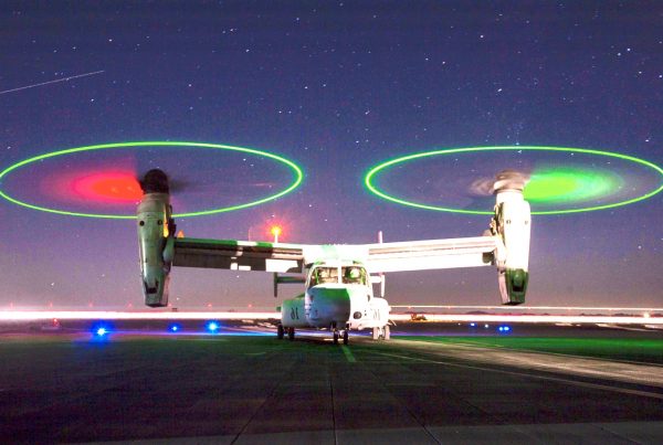
AERIAL AIRBORNE MODELS,
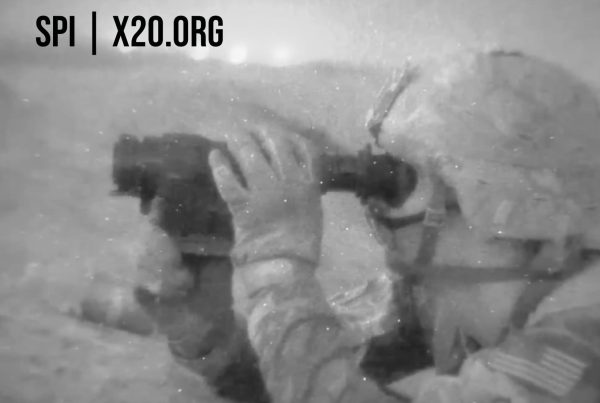
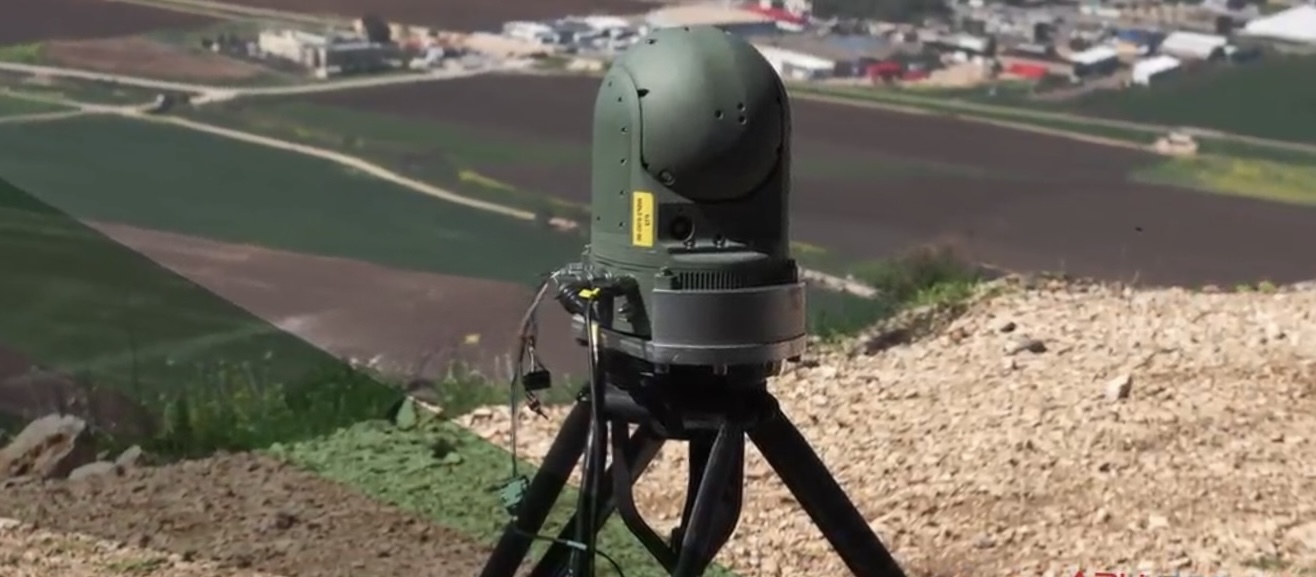
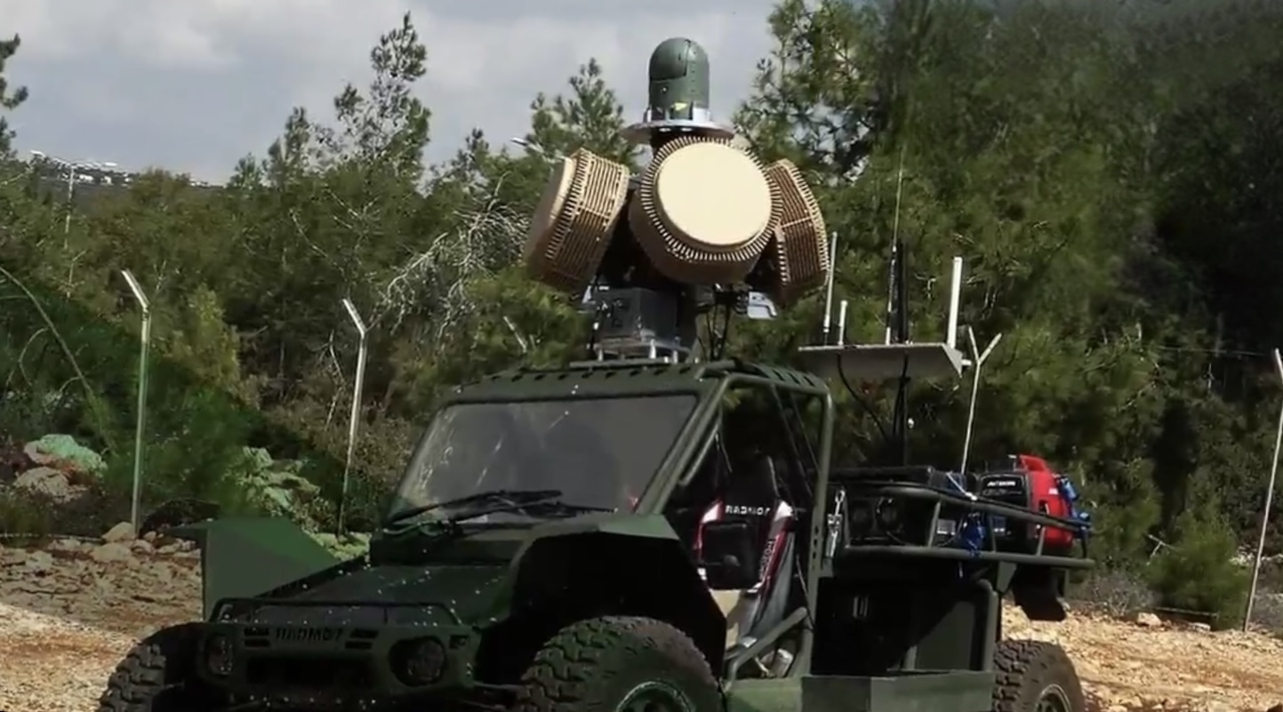
GROUND BASED LAND VEHICLE MODELS AND
MARITIME MARINE OCEAN GRADE SEA VARIANTS


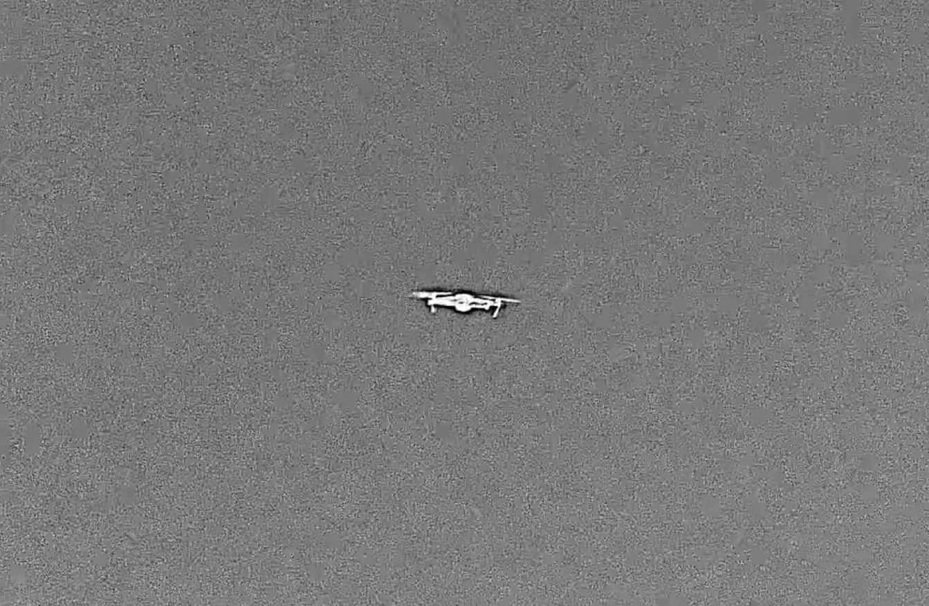
SMALL DJI MAVIC2 UAV at 558 meters range

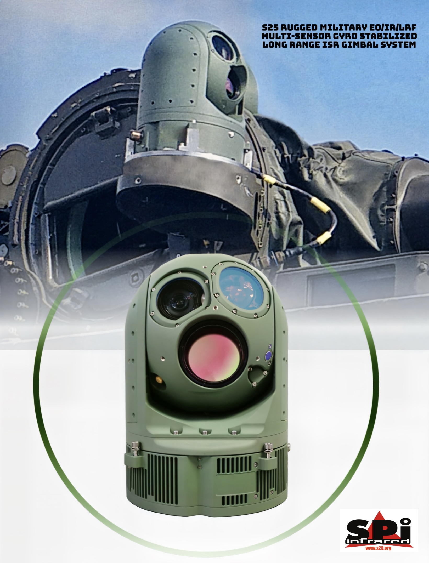
SYSTEM OVERVIEW
This data is a technical description for the high definition (HD) Observation intelligence surveillance recognition (ISR) and weapon director, optronic payload. The payload is refer to as S25-HD.
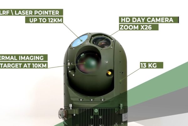
S25-HD is a lightweight long range single LRU, four sensors dual gimbal actively gyro stabilized and remotely controlled. It contains IR sensor, full HD DTV sensor, laser range finder (LRF)and option for laser pointer (LP).
S25-HD is part of the SPI family of HD long range EO/IR all weather rugged ground, naval and airborne multi sensor FLIR Thermal imaging, SWIR, night vision, LLL, LRF, visible zoom payloads which are used successfully on board of variety ground armored vehicle and marine crafts used in military and par-military applications. The S25-HD is under full rate production and is available to select customers on GSA Schedule
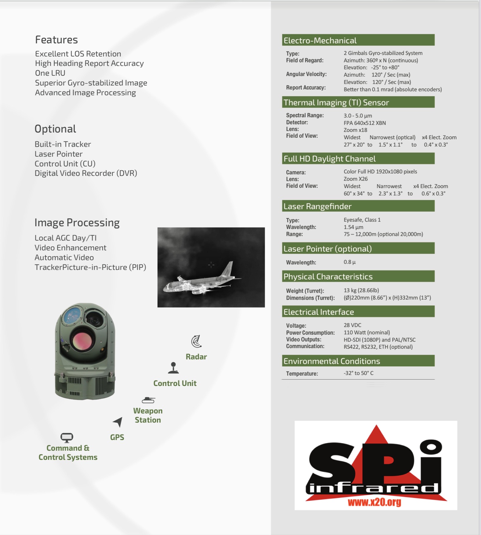
The EO full HD consists of a 1920×1080 pixels sensor (1080p). The long range thermal IR detector is a 640×512 focal plane array (FPA) pixels. An eye safe, laser range finder (LRF) sensor. All are mounted on the line of S25 (LOS) of the payload, aligned with the EO and IR images.
This video output is carried over HDSDI interface. In addition, analog standard (NTSC or PAL) video is output simultaneously and in parallel to the HD-SDI. The two scene images IR and DTV can be monitored simultaneously on the user monitors.
The payload is controlled by computerized control unit (CU) and power by a standard military (ground vehicle or naval craft)24/28 DC voltage supply
Dual gimbals axes, actively stabilized line of S25 (LOS).
Thermal MWIR FLIR imager with long range continuous zoom and alternative four pre-set discrete optical FOVs.
DTV LLL Low Light Level night vision camera with continuous zoom and Near IR capability, with image enhancement.
Simultaneously two switchable composite analogue standard video (AV) outputs, one for-the IR camera and one for the EO camera.
DTV LLL CMOS Visible EO and IR images enhancement algorithm.
Eye safe laser range finder LRF that measures range to viewed target.
Remote control via serial bi-directional communication. Also available is a dedicated JoyStick (JS) that allows a direct control on payload. Alternatively PC with dedicated Man Machine Interface (MMI) console.
Full HD screen of the maximum diagonal (inches), depending on the space available.
Operates from standard armor vehicle or naval craft power source of 28 VDC.
The System has been chosen for use in Military applications, the sensors and optics are hand selected for the finest properties, the mechanical components are second to none.
This fully robust system is a proven powerhouse which is battle proven in multiple military/Homeland security, border, marine, security, surveillance & Related applications.
| Doc. No. | Description |
| MIL-STD-810E | Environmental Test Methods and Guidelines. |
| MIL-STD-704E | Aircraft Electrical Power Characteristics |
| MIL-STD-461 | Electromagnetic Compatibility |
| EIA-RS-422-A | Electrical Characteristics of Balanced Voltage Digital Serial Interface Circuits. |
| EIA-RS-170 | Electrical performance standards monochrome television studio facilities. per NTSC (768×480). |
| CCIR | Electrical performance standards monochrome television studio facilities. per PAL (756×576) |
| SMPTE 292M | Video format HD-SDI 1920x1080p25/30. |
| IEC60825 | Laser devices safety requirements. |
The long range payload supports the following modes of operation:
Power-up: The payload completes power up Gimbals are powered in idle mode. Full communication is established. All sensors are active. IR cooler runs TI and DTV output image.
LRF and LP are blocked from output energy.
Rate: The ultra long range thermal and visible LOS is locked on to a specific inertial direction in Gimbal servo loops are active and the LOS is stabilized. Rate commands will slew the LOS in elevation or in yaw.
Position: The LOS is locked at a fixed angle relative to the carrying Gimbal servo loops are active and the LOS is stabilized. Rate commands will slew the LOS in elevation or in yaw.
Forward: The LOS is locked at a fixed angle relative to the carrying platform forward (0 Az & 0 El). Gimbal servo loops are active and the LOS is Rate commands are ignored.
Stow: The LOS is locked in a back and maximum upward position in order to protect the system windows during idle (Such or non- operation travel of the platform).
Laser Ranging: LRF fires measures and report range to target at center of the To range, LRF must be at active ARM state.
Slave:LOS pointing is slaved to an external source of AZ & EL data, typically maritime
3.2.1 Power
The payload is powered by a 24VDC vehicle power supply (22-32) in accordance with MIL-STD-704E. Power consumption at nominal operation, is less than 80 Watts. Maximum is less than 120W and peak power at start up is less than 180W.
3.2.2 Communication
Communication control and status to/from the payload is via a serial RS-422 bi-directional full duplex channel at 115,200 BPS. The protocol contents are in accordance-with SW Protocol document.
Communication supports the required data rate for gunnery control.
3.2.3 Electrical ICD
The payload interfaces via the following functional connectors.
J1: Serves as the input/output Payload power and signals connector.
J2: Serves for HD-SDI video format, output.
J3:Serves for maintenance purposes.
3.2.1 Video Interface.
The payload interface with the following video outputs
3.2.1.1 HD Format.
Full HDSDI format, switchable between DTV and IR. SMPTE 292M format of 1920x1080p25/30.
3.2.1.2 Analog video (AV) Video Format.
Two AV video outputs are available in a standard analogue format of NTSC (or PAL) factory set. The two outputs are available simultaneously. The prime video output carries also the payload build-in overlaid symbology.
3.2.2 Mechanical Interface.
The S25-HD interfaces to its carrying vehicle by means of six screws on the fixed carrying plate, which allows:
High accurate reference plane for direct mount of the payload to the carrying vehicle, or
Use of shock mounts via a”spider style”mechanical
3.2.3 Interface with other sensors:
The S25-HD can be connected with other sensors and radars
3.2.1 Size and weights.
Payload diameter:
Payload height: 332 mm.
Payload weight: 13 Kg. ( 29 lb)
S25-HD Sensors Characteristics
3.3.1 Turret and LOS.
Angular spatial coverage. (for Ball up orientation) Elevation angle dynamic range : +85° to -20°
*note: Below -25° observation capabilities are degraded due to gimbal obstruction
Azimuth angle dynamic range : 360° x N
Rate – azimuth and elevation : ±0.25° to ±60°/sec (FOV dependent) Acceleration azimuth and elevation: > 60°/sec2
Attitude report Accuracy (El and AZ): Better than 0.2 mrad
Angular drift: < 6° /Hr
Typical LOS stabilization level: 15-50 micro radian RMS
3.3.2 IR Sensor
3.3.2.1 Detector Characteristics
Spectral band:
Array format: MWIR 640 x 512 pixels VGA Available in SXGA 1280×1024 MWIR Sensor. 10-micron pitch. Uniformity:
Two points factory correction. One point user access.
Cooler: Close loop linear cooler. Less than 8 min cool downtime.
Table selection: Three user selectable tables. (To cover the operational temperature scene)
3.3.1.1 Field of View
TI Continuous zoom mode: Optical :
27×21 – 1.47×1.17 (X18 zoom).
Electronic X4: 1.47×1.17 – 0.36×0.29
TI Pre-set FOVs.
The TI can operate in four pre-set FOVs (factory set) for fast FOV switch, which can be configured.
3.3.1.2 TI Controls and Modes of operation
TI image has the following image automatic gain level control (AGC):
Automatic: Image quality is set automatically by the system. This selection can be applied on a selected region from the scene.
Local Area: AGC uses a non-linear base algorithm. This selection can be applied on a selected region from the scene.
Enhancer: The user can select to sharpen the image to depict details in the scene.
Manual: The user controls manually the image Gain and Level to depict specific items into scene.
Focus control: Manual control of IR image focus. Automatic when switching FOV, to the last set or to infinity.
Image freeze.
3.3.1 Color DTV Channel
3.3.1.1 Format
The DTV sensor utilizes a Full HD color image 1920×1080 pixels in parallel to standard analogue output. It has a built in image enhancer based on color boost and contrasts enhancement.
3.3.1.2 DTV Characteristics
Number of pixels:
Sensitivity: color 0.4 lux ; B/W 0.1 lux
Focus: Auto / Manual control.
Iris: Auto / Manual. (user selectable F1.6 to F28)
Shutter: Auto (1/15 to 1/10,000).
Gain: Automatic.
Image freeze: Yes.
Lens type : Continuous zoom FOVs:
| a. HD output: | 60 | – 2.1 | Optical Horizontal |
| 2.1 | – 0.6 | Elec. Horizontal. | |
| b. AV output: | 40 | – 0.9 | OpticalHorizontal. |
|
Pre-set FOVs: |
0.9 | – 0.15 | Elec. Horizontal. |
HD output:59, 16, 3, 2.1 Horizontal.
AV output: 22, 6.0, 2.0, 0.8 ImageEnhancer: Color boost, Contrast enhancement.
Near IR: Yes, 0.4 1.1 Micron remote controlled.
3.3.1 Near IR Capability.
The color TV camera provides a Near IR (NIR) monochrome output video. In this mode the camera uses the full spectral band of 0.4 to 1.0 micron with BW image.
This mode is useful in low light environment such as early dawn, after sun set, or street lights ambient.
3.3.2 Video Characteristics
3.3.2.1 Image enhancer.
The payload uses several algorithms on fly to improve the image quality and overcome disturbances that may occur during operational use. These improvements are for theDTV and TI.
3.3.2.2 Local AGC
The Local AGC function provides wide dynamic range of the video image of theThermal and the Daylight cameras. The user can select a ROI from the image in-order to depict details from a selected scene.
The Local AGC function is helpful when the scenery has a wide range of gray levels such as when the imagery includes sea and sky or sea and land, burning objects,etc.
3.3.2.3 Image enhancement
The Image Enhancement function provides video enhancement in the video frame for both the Thermal and the Daylight cameras and brings out details
case of a low contrast video image, which might occur in hazy/low visibility conditions.
3.3.1.1 Edge Enhancement (Sharpness)
The Sharpness function enhances the sharpness of objects edges within the video image for both the Thermal and the Daylight cameras.
The function increases the effective video image resolution and provides a clearer and sharper video image.
3.3.1.2 Picture In Picture (PIP).
In this mode, the center cut of one sensor image is imposed on the lower right side of the other sensor image. This mode gives the user a better orientation and awareness of the scene by using simultaneously data from two sensors
3.3.1 Laser Range Finder (LRF).
S25-HD utilizes a LRF in the eye-safe band technology. It key parameters are:
Wavelength of operation: 1.54 µm (Eye safe) BeamDivergence: <0.65 mrad.
Energy: 2 6 mJ / Pulse
Rate: 1.0 PPS.
Effective Pointing Range: > 10 km Resolution/Accuracy +/- 3 Meters.
Safety Category: I. per IEC60825
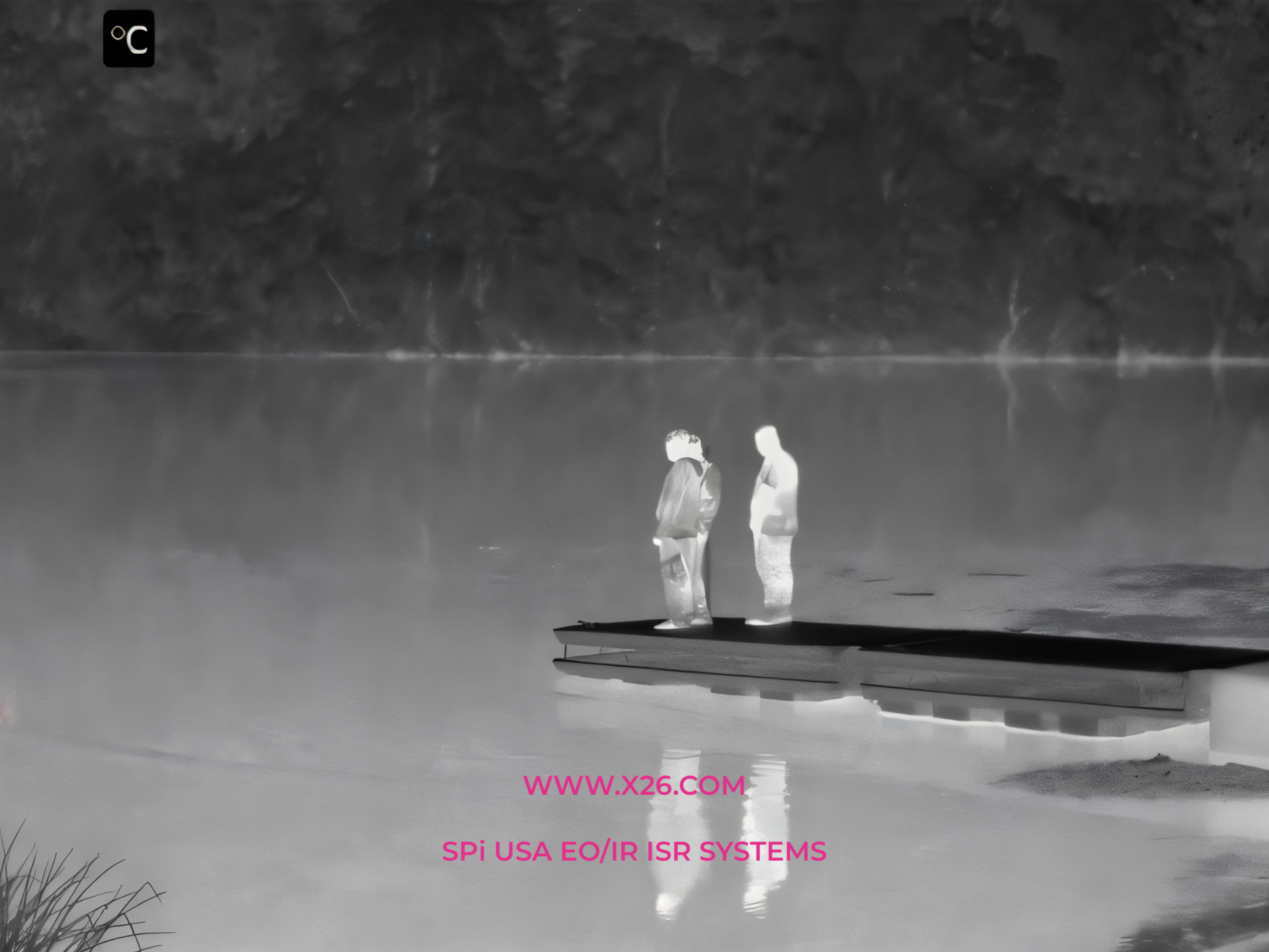
3.3.2 Typical range performances.
The following are typical range performances of the TI and DTV channels of the S25-HD. Ranges are for NATO standard target:
| Target m x m | 2.3X2.3 (NATO) | 0.5×1.8 (Human) | ||
| NFOV | TI | DTV | TI | DTV |
| Detection (Km) | 15 | >18 | 6 | 11.5 |
| Recognition (Km) | 4 | 10 | 1.5 | 4.5 |
| Identification (Km) | 2 | 5.5 | 0.7 | 2.3 |
Overlay Symbology
S25-HD generates graphics and texture which is overlaid on both Analogue video output and HDSDI video output.
This graphics allows the user to better orientate himself while processing the scene and controls the payload. It is possible to declutter part or all the symbology, or change the symbology hue.
Key Symbols In the EO mode:
System mode and
DTVfocus&zoom adjustment
Image enhancement status and
Reticle, unique to each
Turret Gimbal ball payload EOIR LRF Line Of Sight LOS elevation and yaw angular position and slide
Time-and
Tracker symbols: Crosshairs, Window, Predictor
LRF/LP status and range
Menu screen, which allows access to system status and payload
Key Symbols In the IR mode:
System mode and
MWIR Mid-wave Thermal detector sensor cooldown
IR gain, level, focus adjustment slider
Image enhancement status and
Focus adjustment slider
Reticle, unique to each
FOV indication
LOS elevation and yaw angular position and slide
Time and
Tracker symbols: Cross hairs, Window, Predictor
LRF/LP Status and range
Menu screen, which allows access to system status and payload configuration
Environmental Conditions
S25-HD observation unit meets the environmental conditions of typical armor ground vehicle or naval fast small craft. It has been qualified for MIL- STD-810F.
4.1.1 Temperature Operating
Operating:-32Cto+50C per MIL-STD-810E Method3, procedure 2
and Method 502.3, procedure 2.
Storage and Non operating: -40 C° to +71 C° per MIL-STD-810E Method 1, procedure 1 and Method 502.1, procedure 1.
4.1.2 Shock
The payload remains intact and safe after having been subjected to a shock of 20G (½sine 11ms) in any axis. Per 810E 516 I, VI.
4.1.3 Humidity
The payload shall operate without degradation when exposed to humidity of up 95% at ambient of 35 °C, without condensation, during operating, non- operating, storage and transit conditions, Per 810E 507 III.
4.1.4 Blowing Rain
The payload remains intact and safe after having been subjected to blowing rain.
Per 810E 506.3 III.
4.1.5 Vibration
The payload operate and meet the requirements specified when subjected to:
Performance: 1.8Grms for full performance. Endurance: 2.8Grms.
Random vibrations from 5 Hz to 2000 Hz per MIL-STD-810E Method 514.4, category 6, 60 minutes per axis.
4.1.1 Altitude
Operating: Up to +15,000 feet MSL.
Non-operating: Up to +40,000 feet MSL.
4.1.2 Icing
The payload will operate after being exposed and subjected to either Rime or Glaze ice
Delivery.
The S25-HD is packaged in a hard material reusable container. The package shall enable the transportation of the payload via air, ground, or sea cargo. Included with each delivered payload:
Conformance of compliance statements (COC).
Acceptance test log (ATL) reports for each of the subsystems duly filled in and signed.